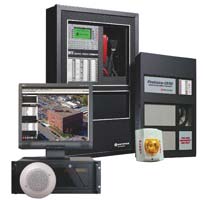
Automatic Fire Alarm Detection System consists of (Conventional / Analogue Addressable) Fire Alarm Control Panel along with Smoke Detectors, Heat Detectors, Beam Detectors, Pull Stations as a Initiating devices as well as Hooter, Siren, Strobes Lights, Response Indicator as a Notification devices. The Control Panel receives signal from Triggered Detector or Pull Station and transmits the signal to the notification device, it also supervise the system wiring and Primary Power Source to the Panel. Auxiliary power supplies (Battery back up) in the Control Panel are required in event of power failure
Addressable Fire Alarm Control Panels employ one or more Signaling Line Circuits, slang - usually referred to as loops or SLC loops - ranging between one and thirty. Depending on the protocol used, a Signaling Line Circuit can monitor and control several hundred devices. Some protocols permit any mix of detectors and input/output modules, while other protocols have 50% of channel capacity restricted to detectors/sensors and 50% restricted to input/output modules. Each SLC polls the device connected, which can number from a few devices to several hunderd, depending on the manufacturer. Large systems may have multiple Signalling Line Circuits
Conventional Fire Alarm Control Panels have been around ever since electronics became small enough to make them viable. Conventional panels are used less frequently in large buildings than in the past, but are not uncommon on smaller projects such as small schools, stores, restaurants, and apartments.A conventional Fire Alarm Control Panels employs one or more circuits, connected to sensors (initiating devices) wired in parallel. These sensors are devised to dramatically decrease the circuit resistance when the environmental influence on any sensor exceeds a predetermined threshold. In a conventional fire alarm system, the information density is limited to the number of such circuits used.
